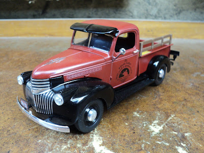
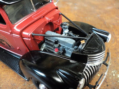
'Still trying to develop a coherent protocol for building plastic kit models. My results to date have not been great. We'll see if I can do better with this one.
I'm thinking along these lines for an orderly approach to kit building:
- Study the plan from beginning to end. Write in the colours alongside the colour code letters. I find it helpful to have the component colours spelled out.
- Nip out all components in order from their trees. Bin them in labelled bins.
- Trim sprue-joins and flash from all components in order.
- Trial fit all components to their mating pieces. Pay close attention to how final assembly will be affected by paint thicknesses.
- Trial assembly to the extent needed to confirm that major subassemblies will go together cleanly. That may require some gluing up that will later have to be taken apart -- a tricky bit of business.
- Rig all components for painting and paint all components in order.
- Final assembly.
Re "2 'n 1" Kit
The '41 Chevy Pickup kit offers stock and custom builds. I'll be building it strictly stock. The custom build variant differs from stock in the following areas:
- Engine rocker cover.
- Engine intake.
- Wheels and tires.
- Horn location.
- - -
Nipping Out
- Generator: It's shown but not called out in drawing No. 1. It's item 31 on the tree with the chassis. It's meant to be semi-gloss black.
- Chrome Door Handle, item 70: There are three of them; only two are needed.
- Drawing No. 8 shows a rectangular opening to be cut in the model's floor. I can't make head or tail of that instruction. I'll just leave that be unless something turns up to give me a reason to do it.
If you build the stock version, you'll have left over:
- Four low-profile tires.
- Four chrome wheels.
- Four inner wheels.
- Chrome rocker cover.
- Chrome air cleaner.
- Dual carburetor.
- - -
Trial Fitting
The model has some ambiguous, iffy fits; examples are item 56, the tie rod, and item 57, the drag link. Beware.
A particularly egregious poor fit is the spare tire carrier, item 19. There's no way to securely close it up at its rear end. I think I'll end up securing it with a loop of 30 AWG copper wire, like so.
It's appalling that I have to do that. It's the sort of kit quality that I'd expect from AMT, not Revell.
- - -
Chassis To Fender Assembly Connection -- SUNDAY, NOVEMBER 18, 2018
The chassis does register to the fender assembly unambiguously, but holding the two together is problematic. A secure connection between those two components is a great help for further trial fitting of the cab and box.
I ended up screwing the two pieces together with a couple of 1.2mm x 4mm eyeglass screws. I used a No. 60 twist drill as a thread-size drill, and a No. 55 twist drill as a clearance-size drill. The polystyrene material is soft enough that the screws can be used as 'threading' screws -- there's no need to tap a female thread. It photographs poorly, but here's a view of the outcome.
Note the two tiny screw heads in the floor of the fender assembly. Those two screws are doing a fine job of securing the fender assembly to the chassis. They'll end up concealed under the cab's seat bottom.
To do such a screw connection, proceed as follows:
- Glue the two pieces together temporarily with minimal applications of CA adhesive.
- On the drill press, drill clear through both pieces No. 60.
- Drill just through the floor No. 55.
- Install the two screws to form the threads.
- Remove the two screws and separate the pieces. Clean up the broken glue join areas.
- - -
Tie Rod And Drag Link -- TUESDAY, NOVEMBER 27, 2018
Everything is painted and ready for final assembly.
 I mentioned earlier that the tie rod's and the drag link's fits are iffy -- I can't make head or tail of how they are supposed to be installed. It looks like I'm just going to omit them entirely. Here's a scan of the pertinent part of the plan.
The parts are items 56 and 57 in section 2.
- - -
'Managed Them After All
Here they are cemented in place.
A bit questionable looking, perhaps, but all together.
- - -
Chassis Completed -- SATURDAY, DECEMBER 15, 2018
Here are some views of the finished chassis.
Note the 30 AWG wire loop securing the rear end of the spare tire holder.
Here's a view of the chassis with the fenders/floor attached.
Bumper-To Chassis Attachment -- SATURDAY, JANUARY 19, 2019
In a word, it's dreadful. It's a nasty piece of bits-and-pieces design that's very difficult to execute well.
Between the ends of the chassis rails and the bumpers themselves, there are four small 'bumper brackets' that must be glued in place. Their fits are ambiguous, and the strength of them is iffy. I did succeed in getting them on more-or-less correctly, but the final bumper attachments will lack truth.
At the rear brackets, I added M1.2 screws for reinforcement. It doesn't photograph well, but here's a view of one screw installation.
It's impossible to do that for the front brackets, and the front brackets are misshapen, resulting in an asymmetrical outcome.
I'd say that the bumper attachment scheme is by far the worst feature of the entire kit.
- - -
Interior Door Handles -- WEDNESDAY, JANUARY 23, 2019
The plan orients the interior door handles so they're pointing frontwards. That's not right -- it makes for what, in reality, would be interference between the door handles and the rotating window cranks. Orient the interior door handles so they're pointing downward or rearward.
Cab Fit
There's something wrong with the fit of the cab on the fender assembly, and I could find no way to correct it.
Note the tilt of the cab; it's evident at the lower edge of the cab. That's with the radiator support correctly installed, and the hood fitting properly. My attempts to understand and correct the flaw were fruitless. I settled on getting the radiator support correctly installed, and the hood's fit to be correct and then living with the tilt to the cab.
- - -
All Done -- FRIDAY, MARCH 22, 2019
Here are some views.
- - -
To be continued.
# # #
# # #


No comments:
Post a Comment